MR-03- Basic MR-03 receiver, use KT-18 ASF radio or KO-Propo module with KO-Propo
radios. This is the standard receiver that racers use. Unfortunately, this is
no longer in production.
MR-03 with Chase Mode with 2 or 3 channel ASF transmitter. Can be used with
KT-18 ASF radio, but need 3 channel PERFEX EX-5UR ASF radio to use the chase
mode. This is no longer in production.
MR-03S - Sports version, use KT-19 FHS radio. This is cheaper with lower quality
circuit board.
MR-03 VE - Brushless version. Use ASF radio like the KT-18. Problem with this
sensorless brushless, is power comes on too suddenly. Sensorless brushless is
ok for dirt, but not ok for on-road racing where you need careful modulation
of power.
The current issue with MR-03 is you either get the low cost MR-03S or MR-03VE burshless. Brushless is too powerful, with sudden power. Low cost sports version is cheaply build circuit board. In another word, there is no real good choice from Kyosho. What is needed is the basic MR-03 board to run good old brushed motor unless someone else comes up with a sensored brushless motor board.
PN is currently building a Spectrum DSM2 compatible board to run brushed motor. It uses a separate programmer that use either iphone or android to program. Can also be programmed from a PC with an optional cable. This is now the best set-up for mini-z.
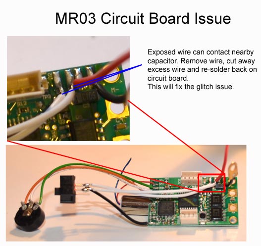
MR-03 issue:
Some have reported that there is a glitch on some MR03. After extensive investigation in the mini-zracer forum, it was discover that the wire for the on/off switch can touch the contacts of the near by capacitor. The solution was to un-solder the wire from the circuit board, shorten the exposed lead and re-solder back on the board. Circuit board is small, so some careful soldering is required. While you are at it, fix both wires for the switch to prevent any issues.
If the wires looks good, you may want to run the car as is. If glitching happens, then fix the wire knowing that is the issue. Otherwise, MR03 is solid.
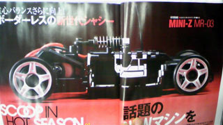
In PN races over in Europe, there has been many rumors about MR-03. In Aug 09 first picture appeared on Mini-ZRacer forum.
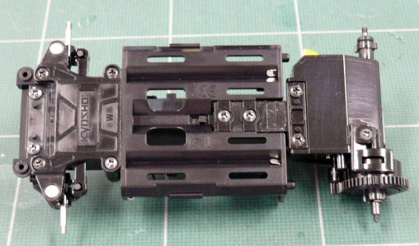
Features of the MR-03
The battery is brought in further towards the center of the chassis. The two main drivers that prevents the battery from moving towards the center line for lower polar moment of inertia is the T-plate and servo motor. Both of them currently sits between the batteries. The current T-Plate on MR-02/015 has two screws lined up laterally in the chassis. The new T-Plate must be more of an "I" plate with mounting screws lined up longitudinally. That would allow the battery to move inward. Second obstacle to moving the battery inward is the steering servo motor. On the MR02, the steering motor is already standing on its side between the battery as narrow as it can be, so there is no room for battery to move in. MR03 has a smaller steering motor.
10/23/2009 was the official release date for the MR03.
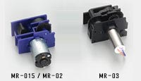
The MR03 has 94.41: instead of 29.34:1 ratio for the MR03. That is a huge difference. The servo motor for the MR03 is much smaller than the MR02 motor. However, the MR03 motor is a coreless design. This means the wires do not wrap around an iron core. There is no detent to the motor. You can spin it freely with the hand. Coreless motor spins faster and have lower inertia that the cored motor. However, this motor would have to spin 3 times faster to match MR02 steering speed. The MR02 steering speed is just about as fast as anyone can humanly turn the steering wheel.
Test with the MR03 and MR02 side by side shows the MR03 to be actually slower than the MR02. It is smoother and more accurate however. This could be due to the fact that per reflexracing's site, MR03 has 87 steps increment than 59 steps for the servo. Therefore, the MR03 turns in increment of about .7 degrees instead of every 1 degree.
One thing to note on the MR03 is that the kingpin on it was highly polished, and the knuckle bore was nicely fiinshed as well. Therefore, when new, there is no stiction for the suspension.