FETs are small component, there are techniques to make working with small parts easy.
For reference, here is a good article by Atomic Mods on how to stack FETs. There are various video on youtube also.
They all make it sound so easy. In reality, changing FETs can be pure hell or relatively easy depending on your technique. I did a lot of trial and error on broken boards. Here are the secrets I found.
Solder - .032" or thinner solder - 62/36/2 with 2% silver bearing kind is prefered. 63/37 is next for low melting temperature. 60/40 rosin solder core may be used if nothing else is found. SMT boards are coated from the factory. Silver bearing solder will replenish that coating during removal and install. For repeated install and removal, silver bearing solder should be used. Look for the solder that advertise as no clean.
Soldering Iron - Small under 20 watt soldering iron is the common choice. However, as long as you can reach the contacts, even a 40 watt iron will work fine. Hint, don't get the very sharp tip type. Is hard to conduct heat to the joint with a sharp tip. Highly recommended is a soldering station. The Hakko 936-12 (-12 is for the medium size 907 handle) is the standard, but unfortunately, they don't make that anymore. However, there are plenty of knock offs that are probably made by the same factory in China! Search "936 solder" on ebay. About $50.
Almost required equipment:
Solder wick - The smallest you can find. Around .030" wide. Chemtronic is suppose to be the best.
Flux - Get a flux pen. Is all you need. Do not use acid flux. For electronic use, almost all are Rosin flux. Use flux that are advertised as no cleaning or no harmful residue would be nice.
Circuit board holder - Is a pain to balance the board on books etc. Typically a iron metal base with alligator clips is good enough. There are more fancy ones out there too.
Magnifying headband - Harbor Freight sells a Magnifier Headstrap with Lights for only $5.99 pretty nice quality works good. So cheap no excuse not to get one. 1.8X,2.3X,3.7X and 4.8X.
Small desk lamp for plenty of light
Nice to have equipment:
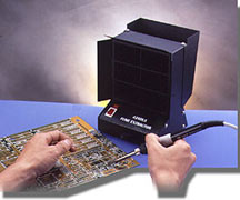
Butane soldering iron with hot air attachment - A Weller P2KC portasol can make a poor man's hot air desoldering tool. Works way better than desoldering wick.
Bausch & Lomb Hastings Triplet 10X Lope - Nice for inspecting the work. Cost around $35 on ebay.
Anti-static work pad - You are suppose to have anti static work surface, but many people have done it without.
Dream equipment:
Desoldering Tweezers (MCM Electronics no longer in business) - Idea sounds good. A heated tweezer to just grab the chip and take it off. Cheap ones were only $33
Flow bench / Fume Extractor - Keep soldering fumes from destroying your brains.
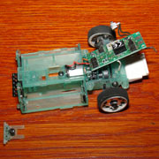
Remove the top cover and switch holder. Flip the circuit board over and hold it in the circuit board holder.
First order of business which is also the most difficult and potentially damaging is removing the old FETs. Remember, once the solder is hot, the glue that glue the electronic trace to the board is already melted and has only about 20% of its original strength. Strong arm removal tactics can cause the circuits to lift off the circuit board. Even if replacement of FETs tracing may break next time you remove the FETs.
FET Removal Options:
Soldering the FET on is actually the easy part. Removal of the FET is where the most damage can occure. There are some of the methods I tried:
Method #4: Use X-Acto knife to cut the legs off of the FET using many pass. This is time consuming and do cause stress to the circuit board tracings. Not recommended.
Method #3: Solder wick to remove most of the solder then pop the component off. Remember to place some liquid flux on the solder wick. Flux works as a wetting agent and works wonders in pulling the solder into the wick. Turn up the heat when using solder wick because the wick conducts a lot of heat away. Use 400F. Use very gentle pressure on the solder iron, otherwise the circuit board glue also gets squeezed out. Is impossible to get rid of the solder under the legs of the FET. Use a pick or small screw driver to pry up one leg at a time.Usually, the chip will pop off hold your breath that the trace does not come with it. Does not work that well.
Method #2: Hot air removal. Most people don't care to spend money on a hot air station, but using a propane solder iron with hot air tip does the job quite well. Practice on some junk circuit boards. Heat until the solder is melted, then just remove the chip. Works like magic. Leaves the circuit looking like new. Might want to have a heat shield to protect that plastic looking box next to the FET. I used some aluminum foil wraped over a business card as a heat shield. The down side to using hot air with the propane solder gun is it takes maybe 20 seconds to heat up the solder to remove it. I would like to apply heat as quick as possible to prevent possible damage to surrounding electronics. On the plus side, hot air makes a very clean removal with minimal stress to the electronic trace. Down side is components around the FET may also be affected. Not really recommended.
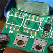
Board looks new after fets are removed. No left over flux from the solder wick or solder.
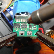
And the best Method #1A: This is what I call the chops sticks technique. If you have two irons, and is not very experianced with soldering, this is probably the best method. Use two soldering iron like a pair of chopsticks. Now, if you want to spend the money, you can buy a hot tweezer that does the same thing. Use a hot tweezer if you want to do this for a living. For the chopstick mothod, use one solder iron on each side to heat all the legs of the chip at the same time, then just pick the chip up using the soldering irons. Clean, fast and simple. Hint: Put a drop of solder on each iron before using it to give it some flux. It will heat the solder joint up almost instantly, and allow you to remove the FET in the minimal amount of time for least impact to the chip and circuit board.
Best Method #1B: If 1A is best method for desoldering, 1B is if you comfortable with solder. Place a blob of solder on the solder iron. Wait for smoke to stop. All the flux will burn off. Put the blob of solder on all the legs on one side of the FET. Do the same to other side. Now, go back and heat one side until solder is melted, then quickly heat the other side until solder is melted on other side too. Go back to first side if necessary. The purpose of the blob of solder is to act as a heat resevoir. It will keep the solder melted while you go from one side to the other. FET just falls off when both solder are melted.
Best Method FET removal chopstick video:
Board Preparation:
Run the solder iron over left over solder on the board to clean up the pad and make the solder bead up.
Install New FETs:
Before soldering new FETs on, you need flux. It will help solder wick underneath the feet on the FETs. Soldering paste works great here. The paste is sticky, and helps in positioning of the FETs also. Liquid flux can be used, but it tend to go away quickly once you start to solder.
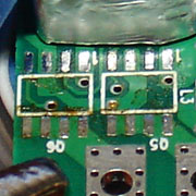
Remember, the dot on the FET goes on the right side in the picture below for both chips. See also the picture on the FETs page. After carefully positioning the fet, put a glob of solder on the iron, and contact the glob of solder onto one leg of the FET. That will melt the solder under the leg to fasten the FET as well as add some more solder to the joint. Do the opposite corner next. Solder another leg or two, then wait for the FET to cool before going on. After all the legs are soldered, re-melt all the solder to get a good joint. Use some liquid flux if some solder are not getting under the feet of the FET. Let the board cool, do the second FET, and you are done.
First drop of solder.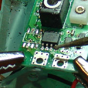 Install
complete
Install
complete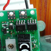
Compare with the factory wave solder job. FET job is definitely not as perfect, but not too bad either. BTW, the solder job on the mini-z is much better than one on the Radio Shack X-Mods.
Factory FET solder.
Tips:
When applying heat to electronic components, use soldering iron with high enough heat so solder melts immediately, and the joint is made in minimal amount of time. Using an soldering iron with too low a temperature will require application of heat to the component for a long time that can leads to damage. To speed up heating up of the joint, place a blob of solder on the tip before touching it to the joint. The blob of solder will allow solder iron to transfer heat faster to the joint so you don't have to hold the iron to the FET for a long time.
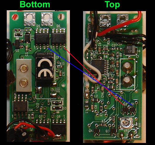
Before powering on for the first time, make sure you verify that all connections are solid. You can blow the FET if the gate connection to the P-Channel is not made when you turn on the power. You will create an instant short in that FET. P-channel depends on voltage to turn off, so if there is no connection, it is always turned on, and when the N-channel is turned on by the controller, then there would be a short. A quick way to check connection is to use an ohm meter. Place one probe on the leg of the FET, and another on the point shown in the circuit board below. Make sure there is continuity.
Useful Links:
Excellent source for difficult to find solder supplies: http://web.archive.org/web/20080123122226/http://www.wassco.com/
Chip Quick - Alternate way of FET removal:
Heated Tweezers - Another way to remove FET: http://www.howardelectronics.com/jbc/microtweezers.html